Power thermistors are components that use the resistance temperature characteristics of NTC thermistors with respect to temperature to suppress inrush current with a large resistance value when power is turned on, protecting components in the circuit.
In addition, in steady-state operation, the self-heating results in low resistance value, enabling efficient power supply to the circuit.
If a resistor is used in a circuit to suppress inrush current, a large voltage drop and power loss will occur due to the resistor during steady-state operation of the circuit. However, by replacing the resistor with a power thermistor, due to the NTC thermistor’s characteristic of decreasing resistance value as temperature rises, during steady-state operation, the resistance value decreases due to self-heating of the NTC thermistor, resulting in a very small power loss. This makes power thermistors a product that contributes significantly to energy conservation and CO2 reduction.
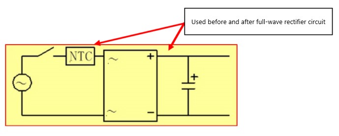
Figure 1 shows a typical circuit example when a power thermistor is used in a full-wave rectifier circuit application.
In Figure 1, the power thermistor is used before the full-wave rectifier circuit (bridge diode), but its performance remains the same even when used after the full-wave rectifier circuit. Power thermistors should be used where inrush current flows in the circuit.
– Fig. 1 Example of a circuit using a power thermistor
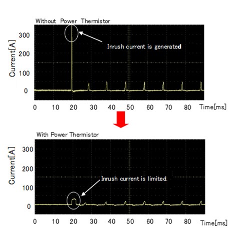
Figure 2 shows, as an example, the inrush current flowing in the circuit and the current waveforms of the inrush current suppressed when a power thermistor is used.
– Fig. 2 Example of inrush current suppression when using power thermistor